
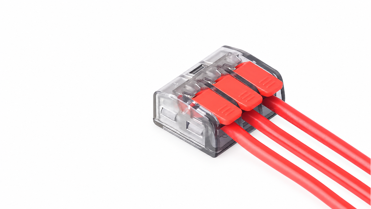
How do lever wire connectors work without a screw holding the conductor? Inside the housing, a shaped spring presses the stripped wire against a conductive metal part. The lever controls the spring, while the housing keeps the parts aligned and insulated.
The Basic Idea
A lever wire connector performs two jobs at the same time:
- It holds the conductor mechanically.
- It creates an electrical path between the connected conductors.
These jobs are related, but they are not identical. The spring provides clamping force. A copper or copper-alloy conductive part provides the main current path in many designs. The housing positions these parts and separates them from anything you should not touch.
You can picture the connector as a small spring-loaded contact chamber. When the chamber opens, you can insert the stripped wire. When it closes, stored spring force presses the conductor into a defined contact area.
This principle appears in many lever connector models, but the internal shapes are not universal. The lever, spring, contact chamber, and conductive path can differ even when two housings look similar.
What Is Inside a Lever Wire Connector?
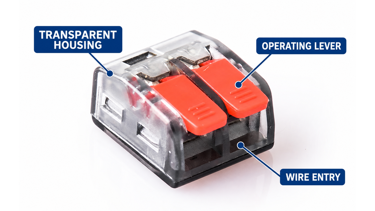
The insulated housing
The housing is more than a cover. It keeps the spring, conductive parts, and wire entry in the correct positions. Internal walls can guide the conductor toward the contact area and help prevent it from entering at the wrong angle.
Many housings are transparent or partly transparent. This lets you see whether the conductor has reached the intended position. The view is useful, but it does not replace the product instructions because some important contact surfaces remain hidden.
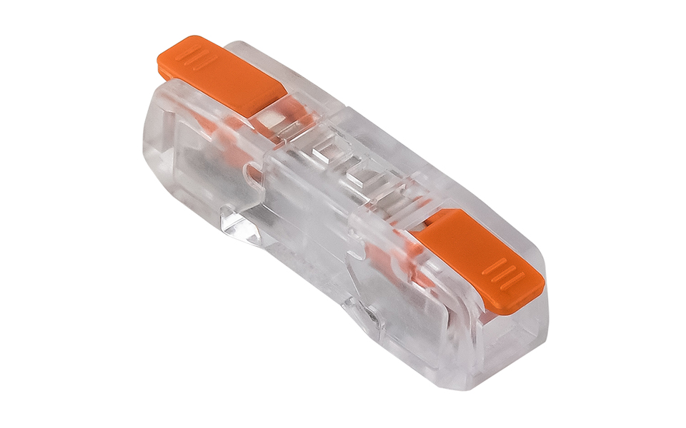
The housing also provides electrical insulation. It does not automatically make the connector waterproof. Moisture, dust, heat, and mechanical protection still depend on the exact product and its enclosure.
The spring
The spring is an elastic metal part. When you lift the lever, the spring bends within its designed range and stores mechanical energy. When you close the lever, the spring presses the conductor against the contact area.
This is why the connection does not need a screw to create clamping force. The shape and material of the spring determine how much it bends, how strongly it presses, and how it responds to the conductor.
The JINH quick wire connector range identifies AISI 301 stainless steel as a spring material used in the category. Exact spring geometry and materials can vary by model, so the category description should not be treated as a drawing for every connector.
The conductive part
Clamping a wire is not enough. Current also needs a continuous metal path through the connector.
In many spring connectors, the stripped conductor is pressed against a copper or copper-alloy current-carrying part. When several ports belong to the same electrical circuit, this metal part links them. If the connector contains separate circuits, the conductive paths remain electrically isolated.
JINH describes tin-plated copper conductive components in parts of its quick-connector range. Copper provides conductivity, while a tin coating can help protect the surface and support a consistent contact interface. The exact alloy, coating, and current-path shape remain model-specific.
The operating lever
The lever is an actuator. It changes the position of the spring so you can insert or remove a conductor. In a typical lever mechanism, lifting the lever moves the spring away from the contact area. Closing the lever lets the spring press the wire into place.
The lever usually does not need continuous hand-applied force. Once it reaches its closed position, the spring geometry maintains the clamp. This explains why operating the lever can feel easy even though the conductor remains held afterward.
The conductor stop and inspection area
Many connectors include an internal stop. It helps position the wire at the intended depth. A transparent section or inspection opening may let you check whether copper has entered far enough.
The stop only works when the wire is prepared correctly. If the stripped section is too short, insulation may reach the contact zone before the conductor reaches the stop. If it is too long, bare copper may remain outside the insulated housing.
What Happens When You Close a Lever Connector?
The complete movement can be explained in five stages:
- The lever opens the clamp. The lever changes the spring position and creates space inside the connection chamber.
- The conductor enters the chamber. The stripped copper passes through the wire guide toward the contact area.
- The lever returns to its closed position. The spring is released from the open position.
- Spring force presses the conductor against the conductive part. The wire is held mechanically and touches the current path.
- The circuit is completed. Current can pass through the connected conductive parts when the circuit is energized.
The spring wire connector range shows how this principle can appear in different housing sizes and port arrangements. The visible lever may change shape, but the important action happens at the spring and conductor contact point.
Where Does the Electricity Actually Flow?
Electricity does not flow through the plastic lever or housing. It follows the connected metal path.
Imagine two conductors inserted into ports that share one conductive bridge:
wire A → contact area → conductive bridge → contact area → wire B
The spring keeps each wire pressed against its contact area. Depending on the design, the spring may also touch conductive components, but you should not assume that it is the main current-carrying bridge. Its primary mechanical role is to maintain contact pressure.
Not every group of holes is internally connected. Some products join all ports to one common potential. Others place several separate circuits inside one housing. The outside appearance may not show the difference clearly.
Before using a multi-port connector, read its circuit diagram or check continuity on a de-energized sample. This tells you whether the product creates one common junction, several independent connections, or an input-to-output arrangement.
Why Does Contact Pressure Matter?
Two pieces of metal may look flat, but their surfaces touch at many microscopic high points. Pressing the conductor against the conductive part increases the real contact area at these points.
More effective contact area generally means lower contact resistance. Lower resistance matters because electrical heating at the connection follows a simple relationship:
Power converted to heat = current² × resistance
This is often written as P = I²R.
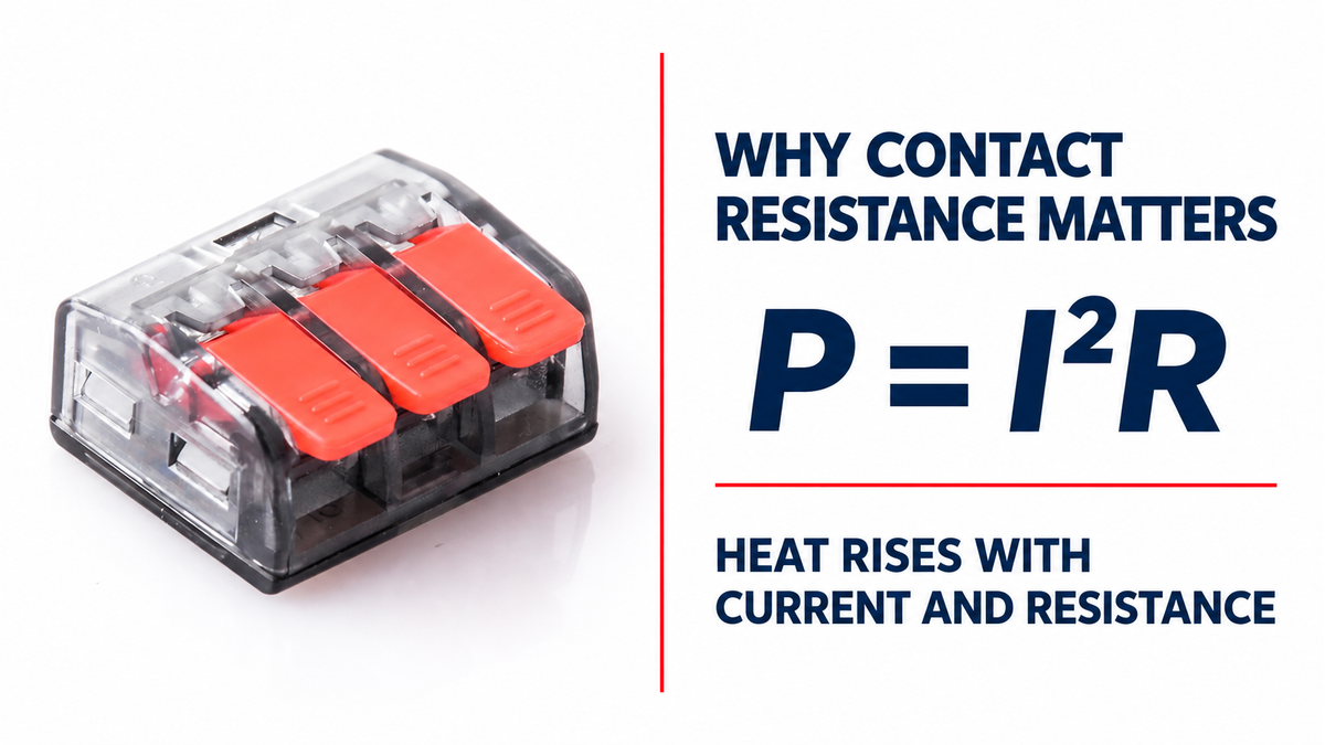
The formula explains why a small increase in resistance can matter more at higher current. It also explains why conductor preparation, insertion depth, spring force, material surfaces, and the rated current all affect the connection.
The formula does not let you calculate a safe connector rating from appearance. Connector ratings come from the complete design and its applicable tests, not from one material or one measurement alone.
Why Can Spring Pressure Adapt to Different Wires?
A spring can move through a designed range while continuing to apply force. This lets one connector model accept more than one conductor cross-section when its contact chamber and spring are designed for those sizes.
A smaller conductor allows the spring to move closer to its resting position. A larger conductor holds it farther open. In both cases, the spring must remain within the movement range intended by the connector design.
This does not mean one connector accepts every wire that physically fits. Solid, stranded, and fine-stranded conductors deform differently. Their permitted size ranges may also differ within the same product.
JINH’s quick wire connector category lists several example ranges, including 0.2–4 mm², 0.5–2.5 mm², and 0.5–6 mm². These examples describe different products, not one universal connector. Always read the model-specific conductor table.
Why Is Strip Length Part of the Mechanism?
Strip length controls where the copper and insulation sit inside the chamber. It is a geometric requirement, not a cosmetic preference.
- Too short: The insulation may enter the clamp, reducing metal-to-metal contact.
- Correct length: Copper reaches the contact area while the housing covers the exposed section.
- Too long: Copper may remain visible outside the housing, reducing touch protection and spacing.
The JINH category page gives 10 mm, or 0.39 inch, as a general reference for its quick wire connectors. Other JINH connector pages show different strip lengths. Use the value printed on the exact product or stated in its datasheet.
What Changes When Temperature or Vibration Changes?
Metal and plastic parts expand and contract as temperature changes. Conductors can also move slightly when equipment vibrates. A spring contact is designed to keep applying force while small dimensional changes occur within the product’s rated conditions.
That does not make the mechanism unlimited. Excessive heat can change material properties or damage the housing. Strong movement can transfer force into the wire entry. Contamination can also interfere with the contact surface.
This is why the operating principle and the product rating answer different questions. The principle explains how the connector works. The rating tells you the conditions under which the complete model has been designed and evaluated to work.
Why Are Lever Wire Connectors Used in Different Applications?
The same basic mechanism can be packaged in several shapes and circuit layouts. That makes spring connections useful where you need compact wiring or repeated connections.
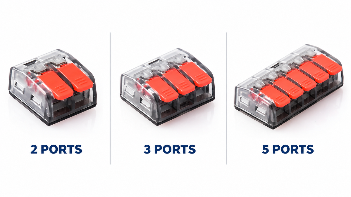
On the JINH product page, example applications include light fixtures, switches and outlets, junction boxes, LED lighting, industrial control cabinets, and pre-wired cabling systems.
The mechanism provides different practical benefits in each case:
- In a light fixture, a compact housing can fit beside the driver and internal wiring.
- In a junction box, several defined ports can organize a common connection.
- In a control cabinet, spring actuation can support repeated assembly without a screw-tightening step.
- In pre-wired equipment, a consistent connector layout can simplify the assembly sequence.
The application still has to match the exact conductor, circuit, enclosure, and product rating. Understanding the mechanism helps you read the product information, but it does not replace it.
What the Mechanism Does Not Tell You
Looking at the spring or operating the lever cannot confirm every specification. The mechanism alone does not tell you:
- Rated voltage or current
- Permitted conductor material and construction
- Exact wire-size range
- Temperature rating
- Number of independent circuits
- Environmental protection
- Certification coverage
- Whether repeated reconnection is permitted
These points belong to the exact model documentation. Two connectors can use a similar spring idea while having different ratings, materials, dimensions, and intended uses.
Conclusion
A lever wire connector works by using stored spring force to press a stripped conductor against a conductive path. The lever, housing, and wire guide control that contact. Once you understand these roles, product drawings and wiring instructions become much easier to read.
FAQ
Does the lever carry electrical current?
The plastic lever normally acts as a mechanical control, not as the current path. Current flows through the conductor and internal conductive metal parts. The exact metal arrangement varies by connector design.
Does the spring carry the current?
The spring may touch conductive components, but its main role is to create contact pressure. Many designs use a separate copper or copper-alloy part as the primary current path. Check a cutaway or technical drawing for the exact model.
What happens if the lever is not fully closed?
The spring may not reach its intended clamping position. The conductor can then have less contact pressure or may not be held correctly. Close the lever completely and check the conductor position before the circuit is energized.
Can you reopen a lever connector after inserting the wire?
Many lever connector models are designed to be opened again, but the permitted number of operations is model-specific. De-energize the circuit and follow the instructions for the exact connector.
Are all ports inside a lever wire connector connected together?
No. Some connectors create one common junction, while others contain several isolated circuits. Check the wiring diagram, product marking, or continuity of a de-energized sample before use.
Why is the housing transparent?
A transparent housing can help you see the conductor position and exposed copper. It supports visual inspection, but it cannot show every hidden contact surface or confirm the electrical rating.
Why must the wire be stripped to a specific length?
The copper must reach the contact area while the housing still covers the exposed section. Incorrect strip length can place insulation inside the clamp or leave bare copper outside the housing.
Why does the lever open before the wire is inserted?
Opening the lever moves the spring away from the contact area and creates space for the stripped conductor. Closing it releases the spring so the conductor is pressed against the internal conductive part.


