
Heavy Duty Connectors
A 16 A Equipment Connection With a Defined Conductor Range Your equipment connection needs to match the wiring and fit the machine layout. JINH heavy duty connectors bring the existing industrial product into a focused collection. Review the published electrical information, conductor range and complete mating arrangement so you can specify the connection your equipment actually needs.
Quick Quote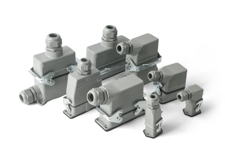
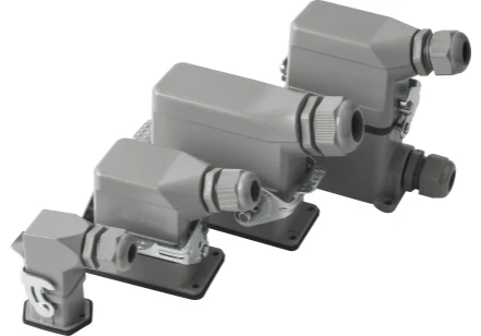
JINH Heavy Duty Connectors for Equipment Wiring
The Features section of the existing Heavy Duty Connectors product page lists 400/500 V, a rated current of 16 A and a conductor range of 0.5–4.0 mm². Conductive parts are described as copper. These details provide a starting point for reviewing the listed product; they should remain associated with its confirmed configuration.
| Existing product detail | Information to review |
|---|---|
| Listed voltage | 400/500 V; confirm the value applicable to your configuration |
| Rated current | 16 A |
| Conductor cross-section | 0.5–4.0 mm² |
| Conductive parts | Copper |
| Product context | Industrial equipment and machinery connections |

How Heavy Duty Connectors Form an Equipment Interface
A heavy duty connector provides a defined electrical interface between equipment wiring sections. The matching contact arrangement carries the assigned circuits across that interface, while the complete assembly places those contacts within the equipment connection. Your wiring schedule identifies what each position does and how the connection belongs in the machine.
For the existing JINH product, the published features list a rated current of 16 A, a conductor cross-section range of 0.5–4.0 mm² and copper conductive parts. The stated voltage information is 400/500 V; use the confirmed value for the supplied configuration. These details describe the existing product and do not establish additional insert families or connection technologies.
Keep the mating parts and conductor positions together in the equipment documentation. This lets your purchasing, assembly and maintenance teams identify the same connection. The complete arrangement matters: a current marking alone cannot identify the required contact layout, mounting dimensions or matching half for your machine.
Send Inquiry Now
An Equipment Connection Built Around Your Wiring Layout
The published conductor range gives you a practical starting point when your machine wiring uses 0.5–4.0 mm² conductors. Together with the listed 16 A rating, it lets you compare the existing product with a defined electrical requirement. Confirm the exact assembly before approving it for a circuit; the equipment connection should be specified as a complete item.
Locate the connector where the surrounding machine leaves room for assembly and later access. Show the cable approach and support on both sides. This helps you integrate the connection into the equipment layout without forcing a sharp bend or transferring unintended pulling loads to the wiring.
The existing product is presented for industrial equipment and machinery. Keep that scope when planning your application. If your specification calls for a particular protection level or housing material, request documentation covering the proposed assembly. Keep that confirmation with your equipment records so your repeat orders identify the same connection and its approved operating conditions.
Industrial Automation Equipment
Review the existing product where your automation equipment needs a defined electrical connection. Begin with the equipment wiring schedule and compare it with the confirmed connection arrangement. Keep the product reference in the equipment record so purchasing, assembly and maintenance can identify the same item.
Machinery Connections
Assess the connector as part of the machine layout, including cable access and the required operating conditions. Your selection should cover the actual supplied assembly rather than a housing description alone. Use the existing product information to start the review and close any remaining specification questions before purchase.
For the broader connection collection, see Waterproof Connector. If your equipment uses a different interface, review the existing aviation plug connector product. For electrical selection background, read Connector Current Rating vs Wire Ampacity, then apply the confirmed limits of your selected product.
Application Scenario
Industrial Equipment and Machinery Connections
Three Defined Product Features
16 A Rated Current
The listed rating gives you a concrete electrical value to compare with your equipment connection requirement for the confirmed configuration.
0.5–4.0 mm² Conductor Range
The published wire range lets you begin the fit check against the conductors already selected for your equipment.
Copper Conductive Parts
The stated conductive material provides a specific product construction detail for your purchasing and engineering review.
Resource


Heavy Duty Connectors FAQ
Do not assume compatibility from the category name or a similar overall size. Identify the original insert and housing, then request confirmation of the proposed combination. If the existing parts cannot be identified reliably, have the complete connection assessed rather than ordering an insert from appearance alone.
Do not treat the product as a switching or load-breaking device unless the exact documentation explicitly establishes that function. Use your equipment’s approved isolation procedure before disconnection. A connector selected for carrying current in service should not automatically be assumed suitable for interrupting that current during maintenance.
Check the maintenance instructions for the exact product before applying a lubricant. Do not assume that an oil or spray used elsewhere on the machine is suitable for connector materials or contacts. Have the cause of the stiffness assessed and use only a treatment confirmed for the affected parts.
No explosion-protection approval is established by the description heavy duty. If your equipment requires such approval, identify the precise requirement and request supporting documentation for the exact assembly. The product should be assessed against that requirement before selection; an industrial application description is not a substitute for evidence.
First establish that the machines use the same confirmed connector configuration and wiring arrangement. Keep the spare identified with its part reference and the equipment it matches. Similar machine exteriors do not prove that their connections are identical, particularly where the machines have been modified or built in different versions.
Have the circuit isolated and the affected connection assessed under your maintenance procedure. Record the location and condition before replacing parts, so the cause can be investigated. A new component alone may not address the underlying issue; the wiring, connection condition and operating load need appropriate review before service resumes.


