
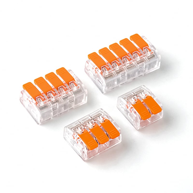
Connector current rating and wire ampacity are different limits. A wire may carry a stated current under one installation condition while the connector has a lower tested rating. Your circuit must stay within the lowest applicable limit after temperature, conductor size, loaded positions, and installation conditions are considered.
The Short Answer
Wire ampacity describes the current a conductor can carry under defined conditions without exceeding its temperature limit. Connector current rating describes the current a connector or terminal can carry under its stated test and use conditions.
Neither value replaces the other.
If a 32 A conductor is connected through a 24 A connector, the connection is not a 32 A circuit. If a connector is rated 32 A but the chosen conductor and installation method allow less, the connector label does not increase the wire’s capacity.
Use this rule:
Allowable circuit current ≤ the lowest applicable rating in the complete current path
That path may include the conductor, contact, connector body, terminal block, PCB trace, busbar, fuse, breaker, switch, and equipment terminal.
What Is Wire Ampacity?
Wire ampacity is the permitted current for a conductor under specified conditions. It depends on more than copper cross-section or AWG size.
Relevant conditions can include:
- Conductor material
- Cross-section or AWG size
- Insulation temperature rating
- Number of current-carrying conductors
- Ambient temperature
- Cable grouping or bundling
- Installation in free air, conduit, tray, or equipment
- Applicable wiring rules and equipment requirements
This is why a single wire-size chart cannot give a universal current value. The same conductor may have different allowable current in different installations.
For connector selection, wire ampacity answers: “Can this conductor carry the planned current in this installation?” It does not answer: “Can this connector carry the same current?”
What Is Connector Current Rating?
Connector current rating is the current assigned to the connector under defined conditions. It reflects the performance of the complete contact system, not just the metal cross-section you can see.
The rating can depend on:
- Contact material and plating
- Contact geometry and contact resistance
- Spring or screw clamping force
- Conductor size and construction used in testing
- Number of circuits carrying current
- Housing material and temperature limit
- Ambient temperature
- Airflow and enclosure conditions
- PCB copper and trace design for wire-to-board products
- Test standard and allowed temperature rise
A data sheet may call the value rated current, nominal current, maximum current per contact, or current-carrying capacity. These terms can use different test conditions, so read the notes beside the number.
Why a Wire Can Fit but the Current Rating Still Does Not Match
The terminal opening and the electrical rating answer different questions.
The wire range tells you which conductors the connection system is designed to clamp. The current rating tells you how much current the complete connector can carry under stated conditions. A connector may accept several wire sizes, but that does not mean every size supports the maximum connector current in every application.
For example, a connector may accept both a smaller and a larger conductor. The larger wire can reduce conductor heating, but it does not remove heat generated at the contact interface. The smaller wire may fit correctly while becoming the lower limit in the final circuit.
This is why “the wire fits” and “the connector is rated high enough” must be checked separately.
Where Does Heat Come From?
Every electrical connection has some resistance. Current passing through that resistance produces heat:
P = I²R
The squared-current term matters. If current doubles while resistance stays the same, heat produced at that resistance becomes four times larger.
Contact resistance can be influenced by conductor preparation, insertion depth, torque, spring force, surface condition, material, and manufacturing consistency. The lever wire connector mechanism article explains how spring pressure holds a conductor against the current path. Current rating adds the next question: how the complete connection behaves electrically and thermally under load.
You should not calculate a safe connector rating from a resistance value and the formula alone. The housing temperature, adjacent loaded contacts, conductor heating, and test limits also matter. Use model-level rating and derating data.
Why Do Loaded Positions Matter?
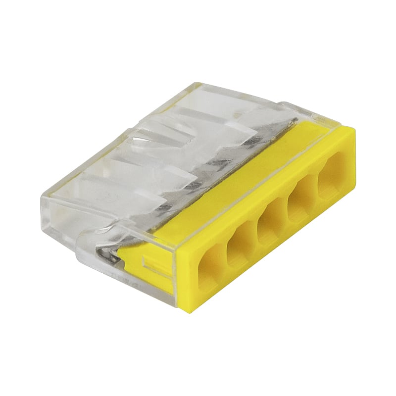
A two-position connector and a multi-position connector may not dissipate heat in the same way. When several neighboring contacts carry current, each contact heats itself and also receives heat from nearby positions.
Manufacturer test data may therefore state:
- Current per contact with all circuits loaded
- Different values for different circuit counts
- A derating curve by ambient temperature
- A specific conductor size used for the test
Molex product specifications provide examples where the permitted current changes with wire gauge and the number of powered circuits. Phoenix Contact publishes connector derating curves that also change with the number of positions.
When you compare products, do not place one “maximum current” number in a spreadsheet without its conditions. Record the circuit count, conductor, ambient temperature, and loading pattern beside it.
How Ambient Temperature Changes the Result
A connector has less room for additional heat when the surrounding air is already hot. Current-carrying capacity can therefore decrease as ambient temperature rises.
This is especially important inside:
- Enclosed control panels
- Lighting fixtures near drivers or lamps
- Compact junction boxes
- Equipment with several heat-producing devices
- Outdoor enclosures exposed to solar heating
The temperature printed for a product may be an operating-temperature range, not a promise that full rated current is available at the highest temperature. Look for a derating curve or a manufacturer statement that links current and ambient temperature.
If no derating information is available, do not invent a universal percentage reduction. Provide the real ambient condition and loading pattern to the supplier and request model-specific confirmation or test evidence.
Rated Current Is Not the Same as Short-Circuit Rating
Continuous current and short-circuit performance describe different conditions.
- Rated or nominal current relates to normal current carrying under stated conditions.
- Short-time withstand current relates to a high current for a specified short duration under defined test conditions.
- Short-circuit current rating (SCCR) describes the suitability of equipment or a component assembly for a stated available fault current under specified protection and conditions.
Do not use a high short-circuit value as the continuous current rating. Also do not assume that a standard distribution block provides overcurrent protection. The protective device and distribution component have separate functions.
If your project needs an SCCR value, request the exact model data, required upstream protection, and applicable combination conditions. A current rating alone does not establish the assembly SCCR.
Rated Voltage Does Not Increase Current Capacity
Voltage rating and current rating address different design limits.
Voltage rating is connected to insulation, spacing, dielectric performance, and the intended electrical system. Current rating is strongly connected to conductive losses and temperature rise.
A connector marked 450 V and 32 A is not a 32 A connector because the circuit operates at a lower voltage. Likewise, using the connector below its voltage rating does not allow you to exceed its current rating.
Check both values independently. Then check surge or impulse requirements where the application requires them.
How to Compare Connector Current Data
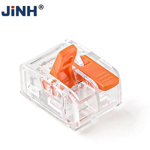
Use a structured comparison instead of one current column.
| Data field | Why it matters | Question to ask |
|---|---|---|
| Rated current | Establishes the stated connector limit | Under which standard and conditions? |
| Current per contact | Clarifies multi-position products | Is the value per circuit or for the complete product? |
| Test conductor | Affects conductor and contact heating | Which AWG or mm² size and conductor type were used? |
| Loaded positions | Shows thermal interaction | Were all circuits powered? |
| Ambient temperature | Defines available thermal headroom | Is there a derating curve? |
| Allowed temperature rise | Explains the test endpoint | What limit was used? |
| Wire range | Confirms mechanical conductor compatibility | Are solid, stranded, and ferruled ranges different? |
| Operating temperature | Defines material-use limits | Does full current apply across the complete range? |
| Voltage rating | Confirms insulation-system suitability | Which AC/DC and standard conditions apply? |
| Certification scope | Supports target-market approval | Does it cover this exact model and rating? |
This table also helps you compare quotations fairly. One supplier may quote a headline maximum under a favorable condition, while another provides an all-circuits-loaded value. The larger number is not automatically the better product if the conditions do not match your use.
How to Select a Connector by Current
1. Define the real load
Record the continuous current, duty cycle, inrush or startup current, and expected overload behavior. A connector for a steady lighting circuit may face a different load profile from a motor-control connection.
Do not use only the power-supply nameplate if branch currents differ. Identify the current through each contact.
2. Define the conductor
Record:
- Copper or aluminum
- AWG or mm² size
- Solid, stranded, or fine-stranded construction
- Insulation temperature rating
- Ferrule or other wire-end preparation
The connector must permit the complete conductor configuration. The wire size alone is not enough.
3. Check wire ampacity in the actual installation
Apply the wiring rules and equipment conditions relevant to the target market. Consider ambient temperature, grouping, enclosure, and the number of loaded conductors.
This step gives you the conductor limit. Keep it separate from the connector limit.
4. Check the exact connector rating
Confirm the model number, current, voltage, wire range, ambient condition, and loaded-position condition. For a family with several port counts, verify whether the rating changes with configuration.
The quick wire connector range includes models with different circuit counts, conductor ranges, and ratings. Treat every model as a separate approval item.
5. Identify the lowest limit
Compare the wire, connector, protective device, equipment terminal, PCB trace, and any distribution component. The lowest applicable value controls the design.
Do not average the ratings and do not select the larger one. A 32 A connector does not compensate for a 20 A conductor limit.
6. Check temperature and grouping
Review the hottest expected location, not only the room temperature. Include nearby power components, enclosure heat, and the number of adjacent loaded contacts.
Request derating data when the application differs from the headline test condition.
7. Validate the assembled connection
Use the production conductor, strip length, ferrule, tool, and assembly method. Evaluate the sample according to the project’s required temperature-rise, voltage-drop, mechanical, and inspection plan.
The sample should prove a repeatable process, not just one successful connection.
Example: One Circuit with Three Different Limits
Assume a circuit contains:
- A conductor with an allowable current of 28 A under the actual installation conditions
- A connector rated 32 A under the relevant model conditions
- An equipment terminal rated 24 A
The circuit does not become 28 A or 32 A. The 24 A equipment terminal is the lowest applicable limit. The design current must remain within that limit and any additional rules for the complete equipment.
Now change the installation so that heat and grouping reduce the conductor’s allowable current to 20 A. The conductor becomes the new lowest limit.
This example shows why current selection is a system check. The controlling component can change when the installation changes.
Current Rating for Distribution Blocks
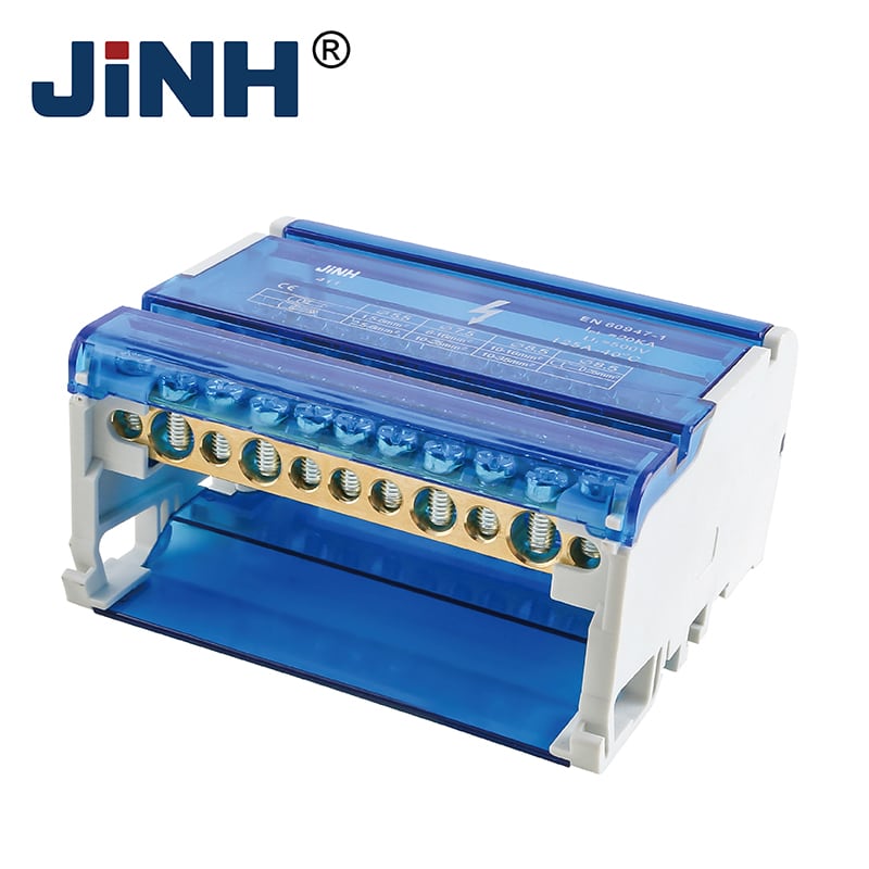
The same logic applies at higher current. A power distribution block can have one incoming terminal and several outgoing terminals with different conductor ranges.
Check:
- Current through the common conductive path
- Current in each outgoing branch
- Line and load conductor sizes
- Copper or aluminum compatibility
- Terminal-specific torque
- Ambient and enclosure temperature
- Required protective devices
- Model-level SCCR data, if applicable
Do not assume that the block’s total current rating applies independently to every output. The circuit diagram and product data must show how current is distributed.
If you are also deciding whether the layout needs a localized block or a longer common power path, see power distribution block vs busbar.
What to Request from a Supplier
Request documents that preserve the test conditions behind the rating:
- Exact model data sheet and drawing
- Rated current and voltage
- Current per contact, where applicable
- Permitted conductor material, size, and construction
- Test conductor used for the current value
- Loaded-circuit or pole condition
- Ambient-temperature or derating data
- Operating-temperature range
- Temperature-rise and voltage-drop test information
- Strip length, torque, and assembly instructions
- Model-level certification scope
- Change-control process for contact, spring, plating, and housing materials
If two documents show different current values, ask which standard, conductor, ambient temperature, and configuration produced each value. Do not select the larger number until the conditions match your application.
Common Mistakes to Avoid
Using a wire chart as the connector rating
A conductor table describes the wire under stated conditions. It does not rate the connector.
Using the largest accepted wire to justify more current
A larger conductor may reduce wire heating, but the connector contact and housing still have their own limits.
Ignoring the number of loaded ports
More adjacent loaded contacts can increase temperature. Compare data for the actual port count and loading pattern.
Treating maximum operating temperature as full-current temperature
The product may remain usable at a stated temperature while requiring lower current. Look for a current-versus-temperature curve.
Mixing voltage and current ratings
Lower voltage does not allow higher current. Approve voltage and current separately.
Applying one rating to every family member
Port count, contact design, wire range, and housing can change within a series. Approve the exact model.
Adding an arbitrary safety percentage
A universal 20%, 25%, or 50% margin cannot replace the actual load profile, wiring rules, derating data, and equipment requirements. Use a margin only when your design standard defines it.
Conclusion
Wire ampacity and connector current rating are separate limits. Define the load, check the conductor in its real installation, verify the exact connector conditions, and use the lowest applicable rating. Model-level data and sample validation give you a more reliable decision than a single headline ampere value.
FAQ
Is connector current rating the same as wire ampacity?
No. Wire ampacity applies to the conductor under defined installation conditions. Connector current rating applies to the connector under its stated test and use conditions. The lower applicable limit controls the circuit.
Can you use a 32 A wire connector with a smaller wire?
Only when the exact model permits that wire material, construction, and size. The smaller conductor must also have sufficient ampacity for the real installation. A connector’s 32 A label does not raise the wire’s allowable current.
Does a thicker wire increase a connector’s current rating?
Not automatically. A thicker permitted conductor may reduce conductor heating, but the contact system and housing still have model-specific limits. Use the manufacturer’s current data for the exact wire and configuration..
Is connector current rating per contact or for the whole connector?
It depends on the product data. Some specifications state current per contact and define how many circuits are loaded. Others give a rating for a complete terminal function. Read the test condition before comparing values.
Why does connector current rating decrease at higher temperature?
Higher ambient temperature leaves less room for additional heat before the contact or insulation reaches its limit. Use the model鈥檚 derating curve or manufacturer guidance for the expected environment.
Does a higher voltage rating mean the connector can carry more current?
No. Voltage rating and current rating address different limits. A lower operating voltage does not authorize current above the connector rating.
What does “all circuits loaded” mean?
It means every stated contact or circuit carries current during the test or rating condition. This can produce more heat than loading only one position, so it is important for multi-port connector comparison.
What should you do when the data sheet shows only one maximum current?
Ask for the conductor size, ambient temperature, loaded-position condition, temperature-rise limit, and applicable standard behind the value. If your application differs, request derating data or suitable test evidence.


