
Waterproof Aviation Plug Connectors
Threaded Mating for Your Cable-to-Equipment Interface When you specify a removable equipment connection, both mating parts need to work together and fit the equipment layout. JINH waterproof aviation plug connectors include the documented SP configurations. Review the contact arrangement, mounting format and matching parts so you can define the complete interface before ordering.
Quick Quote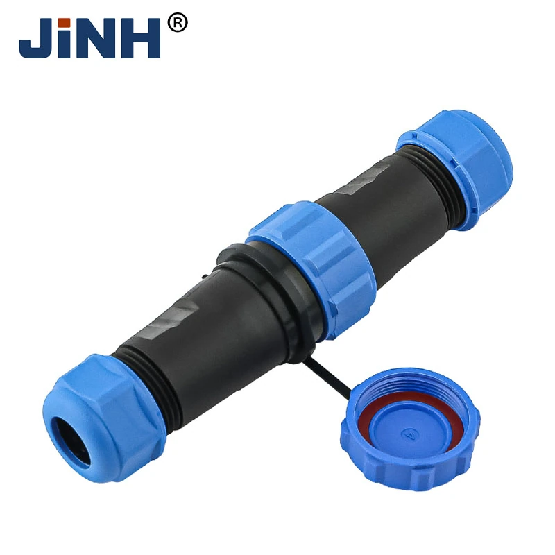
JINH SP Waterproof Aviation Plug Connectors
The existing aviation plug connector product page represents this SP range. The product catalogue includes SP13, SP17 and SP21 configurations. Use the exact model drawing and contact table when comparing these options; the family name alone does not identify the complete assembly you will receive.
Published product information describes threaded mating, solder termination and gold-plated copper contacts. These details help you understand the basic connection structure. Electrical limits and dimensional requirements must still be checked for the selected configuration, because different contact arrangements should not inherit a rating from another item in the range.
| Selection area | What you should identify |
|---|---|
| SP configuration | Complete reference for the intended size and arrangement |
| Contacts | Required count and the assigned function of each position |
| Mating counterpart | Matching part reference for the other side of the connection |
| Equipment mounting | Panel or cable arrangement shown in the selected drawing |
| Electrical limits | Current and voltage data for the specific contact configuration |
| Cable entry | Permitted cable arrangement and dimensions for the selected part |

How SP Waterproof Aviation Plug Connectors Work
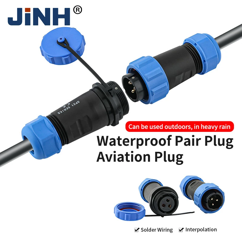
The SP connection uses matching contact halves held together by a threaded coupling. The conductors terminate at the contacts by soldering, and the mating contacts complete the electrical paths when the pair is assembled. You get a defined, removable interface between cable sections or between a cable and equipment, according to the documented configuration.
The product photograph shows a cable-to-cable assembly with cable entries at both ends and a tethered protective cap. That format places the detachable joint along the cable run. Equipment-mounted formats should be selected only from the corresponding catalogue drawing, because the visible inline body does not establish a panel opening or mounting pattern.
Contact arrangement is part of the connection’s identity. Record the assigned function of each position and use the stated viewing direction on the mating-face drawing. With both halves identified together, your assembly team can prepare the conductors around one consistent interface instead of matching circular shells by appearance.
Send Inquiry Now
A Removable Cable Interface for Your Equipment
A threaded mating structure gives your equipment cable a defined connection point. Where your installation needs a detachable link to an external module, sensor or instrument accessory, you can plan that joint where it is accessible during installation and maintenance. The exact contact arrangement and electrical limits determine whether a specific SP configuration fits the job.
The documented SP13, SP17 and SP21 options let you compare configurations within the existing range. Their dimensions and contact tables help you work from your actual equipment layout. Published solder termination and gold-plated copper contact details also give you concrete construction information for the assembly record.
For the cable-to-cable format shown, allow handling space around the threaded coupling and support the cable on either side. For any panel-mounted format, use its own mounting drawing. Confirm the documented protection condition of the selected complete assembly, including the state in which the connection is intended to operate.
Outdoor Equipment Cable Connections
Connect the cable from your outdoor equipment to an external sensor or accessory through a removable inline pair. Keep the joint accessible for equipment replacement, and confirm the selected assembly’s protection conditions for the location.
Industrial Machine Module Connections
Use a matching connector pair between your machine and a separate functional module where installation or servicing requires cable disconnection. Check the conductor functions and electrical limits for the exact SP configuration.
Instrumentation and Test Equipment
Plan a detachable cable link between your instrument and its external probe or accessory. Define the required contact positions before selecting the pair; the connector name alone does not establish suitability for a particular signal.
Industrial Automation Equipment
Consider the SP interface for removable cable connections around your automation equipment. Match the cable routing and contact arrangement to your machine design, with enough access to handle the threaded coupling during servicing.
Visit the Waterproof Connector collection to compare the available interface types. For the general selection sequence, see How to Choose Waterproof Wire Connectors. Use the SP documentation for the final configuration details.
Application Scenario

Outdoor Equipment Cable Connections

Industrial Machine Module Connections

Instrumentation and Test Equipment

Industrial Automation Equipment
Four Features of the SP Aviation Plug Range
Threaded Mating Structure
A threaded coupling secures the matching connector halves and gives the interface a defined mechanical connection.
SP Configuration Choices
The documented SP13, SP17 and SP21 range provides different configurations to compare against your equipment requirements.
Solder Termination
The published termination format lets you plan conductor preparation around the selected contact assembly and its instructions.
Gold-Plated Copper Contacts
The stated contact construction gives you a specific material detail to include in your product review.
Resource


Waterproof Aviation Plug Connectors FAQ
Do not assume cross-brand interchangeability from the size or appearance of the shell. You need confirmation of the complete mating combination, including the contact arrangement and coupling details. If you are replacing an existing connector, identify its original reference before requesting a compatible part or a replacement pair.
No specific aerospace qualification is established by that product name. If your purchase specification requires an approval, ask for documentation identifying the exact product and the required qualification. You should assess that evidence against your project requirements rather than treating a common connector description as a certification claim.
Stop rather than forcing the coupling. Check the mating parts, alignment and visible condition under the product’s assembly procedure. Damaged or mismatched components should be assessed before use. Forcing the thread can make the original issue harder to identify and leave you with a connection that cannot be assembled correctly.
Check the requirements for that unmated part and the permitted protective arrangement. A rating for a completed connection should not be assumed to cover an exposed half. If your equipment is regularly disconnected, include that condition in the inquiry so you can establish how the unused interface should be protected.
Follow the instructions for the exact contact assembly and your approved rework procedure. Repeated heating or damage during removal can affect parts that appear usable from outside. Identify the affected components, inspect them appropriately and confirm whether replacement is needed before you accept the corrected cable assembly.
Specify the contact gender explicitly and include a clear photograph or drawing of the mating face. Terms such as plug and socket may be interpreted differently when they describe housings rather than contacts. Recording the actual contact arrangement helps you communicate the required part without relying on those names alone.


